behaviour Architecture Reference
List of all members.
Processes |
| fsm | ( clk , rstb ) |
| shift_gen | ( clk , rstb ) |
Constants |
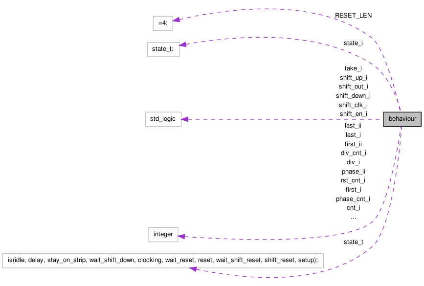
| RESET_LEN | := 4 |
Types |
| state_t | ( idle , delay , stay_on_strip , wait_shift_down , clocking , wait_reset , reset , wait_shift_reset , shift_reset , setup ) |
Signals |
| state_i | state_t |
| div_i | range 0 to 2 **8 |
| div_ii | range 0 to 2 **8 |
| div_cnt_i | range 0 to 2 **8 |
| phase_ii | range 0 to 2 **8 |
| cnt_i | range 0 to 2 **8 |
| first_i | range 0 to 2 **8 |
| first_ii | range 0 to 2 **8 |
| last_i | range 0 to 2 **8 |
| last_ii | range 0 to 2 **8 |
| rst_cnt_i | range 0 to 2 **8 |
| phase_cnt_i | range 0 to 2 **8 |
| shift_en_i | |
| shift_up_i | |
| shift_down_i | |
| shift_out_i | |
| shift_clk_i | |
| take_i | |
Detailed Description
Architecture of VA1 strobe generator.
The strobe generator is initialised by the start signal. It will then start strobing the VA1s after phase clock cycles. Note that there's an implicit delay of 3 clock cycles (= 75ns) from the reception of the start signal.
Note, that the rest of the design may implicitly introduce an additinal delay on the start signal. This must be factored in when tunning the setting of phase.
The period of the strobe is set by the input div, so tha the period is equal to  .
.
The range strips (and consequently the number of strobes) is set by the inputs first and last. If the value of first is changed, then the architecture will set-up the VA1 pointer to that value. That means sending a single shift_clk pulse together with a shift_in pulse (which resets the cursor to the start of the VA1) , and then send first shift_clk pulses.
When start signal arrives, the architecture will send (last - first) strobes, then send a digital reset (dreset) strobe, and then do a setup as outlined above.
Member Function Documentation
| fsm | |
( clk , |
|
|
rstb ) |
[Process]
| shift_gen | |
( clk , |
|
|
rstb ) |
[Process]
Member Data Documentation
cnt_i range 0 to 2 **8 [Signal] |
div_i range 0 to 2 **8 [Signal] |
div_ii range 0 to 2 **8 [Signal] |
last_i range 0 to 2 **8 [Signal] |
state_t ( idle , delay , stay_on_strip , wait_shift_down , clocking , wait_reset , reset , wait_shift_reset , shift_reset , setup ) [Type] |
The documentation for this class was generated from the following file: