rtl Architecture Reference
[Model of ALTRO chip]
Inheritance diagram for rtl:
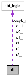
Collaboration diagram for rtl:
Processes | |
| p_sync1 | ( clk , rstb ) |
| p_sync2 | ( clk2 , rstb ) |
Signals | |
| w0_i | std_logic |
| Wire 0. | |
| w1_i | std_logic |
| Wire 1. | |
| r1_i | std_logic |
| Register 1. | |
| r2_i | std_logic |
| Register 2. | |
| r3_i | std_logic |
| Register 3. | |
| x1_i | std_logic |
| Output. | |
| busyb_i | std_logic |
| Busy signal. | |
Detailed Description
Syncronise x2 to clocks clk and clk2
Member Function Documentation
| p_sync1 | ( clk , | |
| rstb ) |
Syncronise to clk
- Parameters:
-
clk Clock to syncronise to rstb Async. reset
- Returns:
- x1_i
| p_sync2 | ( clk2 , | |
| rstb ) |
Syncronise to clk2 Input signal x2 is cascaded through 2 registers (r1_i, r2_i)
- Parameters:
-
clk2 Clock to syncronise to rstb Async. reset
- Returns:
- r1_i, r2_i, r3_i
Member Data Documentation
busyb_i std_logic [Signal] |
Busy signal.
r1_i std_logic [Signal] |
Register 1.
r2_i std_logic [Signal] |
Register 2.
r3_i std_logic [Signal] |
Register 3.
w0_i std_logic [Signal] |
Wire 0.
w1_i std_logic [Signal] |
Wire 1.
x1_i std_logic [Signal] |
Output.
The documentation for this class was generated from the following file:
- altro/sync21.vhd