behaviour Architecture Reference
[Behavoural Model of AD7417 5-channel 10bit ADC]
Architecture of AD7417 model. More...
Inheritance diagram for behaviour:
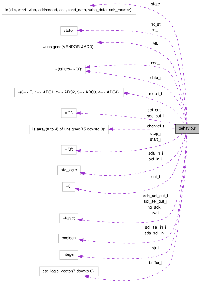
Collaboration diagram for behaviour:
Functions | |
| string | slv2str ( constant v: in std_logic_vector ) |
| Convert std_logic_vector to a string. | |
Processes | |
| start_condition | ( sda_in_i , scl_in_i ) |
| Tristate buffers. | |
| stop_condition | ( sda_in_i , scl_in_i ) |
| Detect stop condition - that is, that the data line goes high while the clock line isn't low. | |
| count_clks | ( scl_in_i , start_i , stop_i ) |
| Count clock edges. | |
| buffer_it | ( start_i , stop_i , cnt_i ) |
| Buffer data. | |
| update_state | ( scl_in_i , stop_i ) |
| Update the state. | |
| fsm | ( start_i , stop_i , st_i , cnt_i ) |
| Get the next state. | |
| decode | ( data_i , start_i ) |
| Decode the instructions. | |
Constants | |
| result_i | channel_t := ( 0 = > T , 1 = > ADC1 , 2 = > ADC2 , 3 = > ADC3 , 4 = > ADC4 ) |
| ME | unsigned ( 6 downto 0 ) := unsigned ( VENDOR &ADD ) |
| channels our addr. | |
Types | |
| channel_t | array ( 0 to 4 ) of unsigned ( 15 downto 0 ) |
| channel | |
| state | ( idle , start , who , addressed , ack , read_data , write_data , ack_master ) |
Signals | |
| scl_sel_in_i | boolean |
| Tri-state select. | |
| scl_sel_out_i | boolean := false |
| Tri-state select. | |
| scl_in_i | std_logic |
| Clock input. | |
| scl_out_i | std_logic := ' 1 ' |
| Clock output. | |
| sda_sel_in_i | boolean |
| Tri-state select. | |
| sda_sel_out_i | boolean := false |
| Tri-state select. | |
| sda_in_i | std_logic |
| Data input. | |
| sda_out_i | std_logic := ' 1 ' |
| Data output. | |
| add_i | std_logic_vector ( 6 downto 0 ) := ( others = > ' 0 ' ) |
| data_i | std_logic_vector ( 7 downto 0 ) := ( others = > ' 0 ' ) |
| rw_i | boolean := false |
| Read-not-write. | |
| start_i | std_logic := ' 0 ' |
| Start condition. | |
| stop_i | std_logic := ' 0 ' |
| Stop condition. | |
| cnt_i | integer := 8 |
| Counter. | |
| buffer_i | std_logic_vector ( 7 downto 0 ) |
| buffer | |
| ptr_i | integer |
| Address pointer. | |
| no_ack_i | boolean := false |
| No acknowledge from master. | |
| nx_st | state |
| State types Next state. | |
| st_i | state |
| This state. | |
Detailed Description
Architecture of AD7417 model.
Member Function Documentation
| buffer_it | ( start_i , | |
| stop_i , | ||
| cnt_i ) |
Buffer data.
- Parameters:
-
start_i Start condition stop_i Stop condition. cnt_i Counter
| count_clks | ( scl_in_i , | |
| start_i , | ||
| stop_i ) |
Count clock edges.
- Parameters:
-
scl_in_i Serial clock start_i Start condition stop_i Stop condition. Increments counter on each rising clock edge
| decode | ( data_i , | |
| start_i ) |
Decode the instructions.
- Parameters:
-
data_i Buffer of data start_i Start condition
- Returns:
- return_i If we saw CFG1 address If we saw a PTR address Counter Base
| fsm | ( start_i , | |
| stop_i , | ||
| st_i , | ||
| cnt_i ) |
Get the next state.
- Parameters:
-
start_i Start condition stop_i Stop condition. cnt_i Counter st_i The state
- Returns:
- the next state
| string slv2str | (constant v in std_logic_vector ) |
Convert std_logic_vector to a string.
- Parameters:
-
v The vector to convert
- Returns:
- String representation of v
| start_condition | ( sda_in_i , | |
| scl_in_i ) |
Tristate buffers.
Detect start condtion - that is, that the data line transition from low to high, while the clock line isn't low.
- Parameters:
-
sda_in_i Serial data input scl_in_i Serial clock
| stop_condition | ( sda_in_i , | |
| scl_in_i ) |
Detect stop condition - that is, that the data line goes high while the clock line isn't low.
- Parameters:
-
sda_in_i Serial data input scl_in_i Serial clock
| update_state | ( scl_in_i , | |
| stop_i ) |
Update the state.
- Parameters:
-
scl_in_i Serial clock stop_i Stop condition.
- Returns:
- the state
Member Data Documentation
add_i std_logic_vector ( 6 downto 0 ) := ( others = > ' 0 ' ) [Signal] |
buffer_i std_logic_vector ( 7 downto 0 ) [Signal] |
buffer
channel_t array ( 0 to 4 ) of unsigned ( 15 downto 0 ) [Type] |
channel
cnt_i integer := 8 [Signal] |
Counter.
data_i std_logic_vector ( 7 downto 0 ) := ( others = > ' 0 ' ) [Signal] |
no_ack_i boolean := false [Signal] |
No acknowledge from master.
ptr_i integer [Signal] |
Address pointer.
rw_i boolean := false [Signal] |
Read-not-write.
scl_in_i std_logic [Signal] |
Clock input.
scl_out_i std_logic := ' 1 ' [Signal] |
Clock output.
scl_sel_in_i boolean [Signal] |
Tri-state select.
scl_sel_out_i boolean := false [Signal] |
Tri-state select.
sda_in_i std_logic [Signal] |
Data input.
sda_out_i std_logic := ' 1 ' [Signal] |
Data output.
sda_sel_in_i boolean [Signal] |
Tri-state select.
sda_sel_out_i boolean := false [Signal] |
Tri-state select.
start_i std_logic := ' 0 ' [Signal] |
Start condition.
state ( idle , start , who , addressed , ack , read_data , write_data , ack_master ) [Type] |
stop_i std_logic := ' 0 ' [Signal] |
Stop condition.
The documentation for this class was generated from the following file:
- ad7417/ad7417.vhd